This article is the 13th in our series of white papers on radiologic patient positioning techniques for x-ray examinations. If you'd like to comment on or contribute to this series, please e-mail [email protected].
For the humerus, anteroposterior (AP) and lateral radiographs constitute the basic examination. Both views should include the elbow and joints of the shoulder, with the elbow manifesting a true lateral configuration in the lateral projection.
Technical factors
- Image receptor (IR): lengthwise (large enough to include the entire humerus) 14 x 17 inch (35 x 43 cm).
- Moving or stationary grid (non-grid detail screen for smaller patients).
- kVp: 70 ± 5 kVp with screen; 65-70 kVp with grid on larger patients.
- mAs: 6.
- SID: minimum of 40 inches (101 cm).
Positioning for an AP projection of the humerus
- Place the patient in an upright-seated or standing position facing the x-ray tube. However, if the patient’s condition doesn’t allow upright positioning, an AP projection can be performed in the supine position.
- Adjust the height of the cassette to place its upper margin about 1½ inches (3.8 cm) above the head of the humerus.
- Abduct the arm slightly, and supinate the hand so that epicondyles of the elbow are equidistant from IR.
- A coronal plane passing through the epicondyles should be parallel with the cassette plane for the AP or posteroanterior (PA) projection.
- Respiration: suspend.
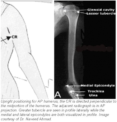
- Central ray (CR): perpendicular to the midportion of the humerus and the center of the cassette.
 |
Evaluation criteria for AP projection of humerus
- AP projection of the entire humerus, including the shoulder and elbow joints.
- Long axis of the humerus should be aligned to the long axis of the IR.
- A true AP projection is evidenced at the proximal humerus by the following:
- The greater tubercle is seen in profile laterally.
- The humeral head is partially seen in profile medially, with minimal superimposition of the glenoid cavity.
- The distal humerus should show both lateral and medial epicondyles visualized in profile.
- CR and center of the collimation field should be to the approximate midpoint of the humerus.
- Optimal density and contrast with no motion and sharp cortical margins. Bony trabecular markings should be demonstrated at both the proximal and the distal portions of the humerus.
Positioning for a lateral projection of the humerus
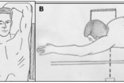
- Place the patient in a seated-upright or standing position facing the x-ray tube. However, if the patient’s condition doesn’t allow upright positioning, a lateral projection can be performed in the supine position.
- Place the top margin of the cassette approximately 1½ inches (3.8 cm) above the level of the head of the humerus.
- Unless contraindicated by possible fracture, internally rotate the arm, flex the elbow approximately 90°, and place the patient’s hand on their hip. A coronal plane passing through the epicondyles should be perpendicular with the cassette plane.
- Respiration: suspend.
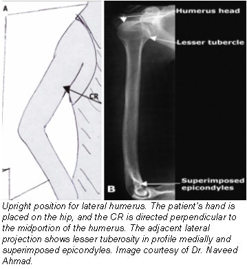
- CR: perpendicular to the midportion of the humerus and the center of the cassette.
 |
Evaluation criteria for lateral projection of humerus
- A lateral projection of the entire humerus, including elbow and shoulder joints, should be visible.
- A true lateral projection is evidenced by the following:
- Epicondyles are directly superimposed.
- Lesser tubercle is shown in profile medially, partially superimposed by lower portion of glenoid cavity.
- CR and center of collimation field should be to the approximate midpoint of the humerus.
- Optimal density and contrast with no motion and sharp bony trabecular markings of entire humerus should be seen.
Radiographic positioning for the clavicle
The radiographic evaluation of the clavicle requires AP and AP axial projections.
Technical factors
- IR: 25 x 30 cm (10 x 12 inch) crosswise.
- Automatic exposure control (AEC) is not recommended.
- Digital IR requires very close collimation.
- kVp: 70 ± 5 kVp range.
- mAs :8.
- SID: minimum of 40 inches (101 cm).
Positioning for an AP projection of the clavicle
- Place the patient in the supine or upright position.
- Adjust the body to center the clavicle to the midline of the table or vertical grid device.
- Place the patient’s arms along the sides of their body, and adjust their shoulders to lie in the same horizontal plane.
- Center the clavicle to the cassette.
- Respiration: suspend at the end of exhalation to obtain a more uniform-density image.
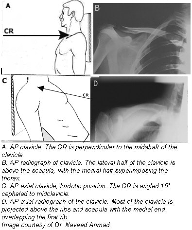
- CR: perpendicular to the mid-clavicle.
 |
Positioning for an AP axial projection of the clavicle
- Stand or seat the patient 1 foot (30 cm) in front of the vertical cassette device, with the patient facing the x-ray tube. Alternatively, if the patient is unable to stand and assume the lordotic position, place the patient supine on the table.
- If the patient is in the standing lordotic position, have the patient lean backward in a position of extreme lordosis, and rest the neck and shoulder against the vertical grid device. The neck will be in extreme flexion.
- Center the clavicle to the center of the cassette.
- Respiration: suspend at the end of full inspiration to further elevate and angle the clavicle.
- CR: 15°-30° cephalad to mid-clavicle. Thinner patients will require more angulation to project the clavicle off the scapula and ribs. For the standing lordotic position, 0°-15° is recommended. For the supine position, 15°-30° is recommended.
Evaluation criteria for the clavicle
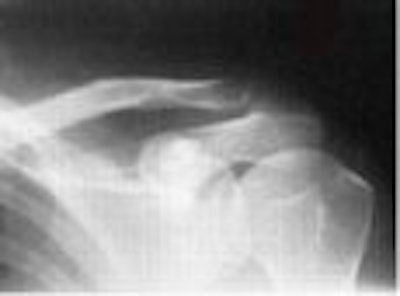
- On a true AP projection, the lateral half of the clavicle should be seen above the scapula, with the medial half superimposing the thorax.
- On an AP axial projection, most of the clavicle should be projected above the scapula and ribs. Only the medial portion of the clavicle will be superimposed by the first and second ribs.
- On an AP axial projection, the entire clavicle should be clearly demonstrated in a horizontal placement along with the acromioclavicular (AC) joint and the sternoclavicular (SC) joint.
Radiographic positioning for the AC joint
The AC joint is a small synovial joint between the lateral end of the clavicle and the medial aspect of the acromion of the scapula. It permits both gliding and rotary (elevation, depression, protraction, and retraction) movements. Although the AC joint is visualized in routine views of the shoulder, it may be superimposed on other osseous structures.
Radiographs obtained in the frontal projection with a cephalad tilt of the incident beam of approximately 15° are superior in delineating abnormalities of this articulation. Stress radiographs are frequently necessary to diagnose AC joint subluxation and dislocation.
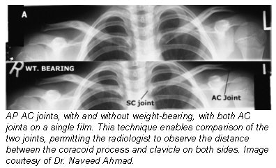
These are obtained by having the patient hold a 2.3-7 kg (5-15 pound) mass (weight) in the hand or tying this weight to the wrist. If possible, it is beneficial to view both AC joints on a single film. This allows comparison of the two joints, permitting the radiologist to observe the distance between the coracoid process and clavicle on both sides.
 |
Technical factors
- IR: 7 x 17 inch (18 x 43 cm) or two 8 x 10 inch (20 x 25 cm), as needed to fit the patient.
- "With weight" and "without weight" markers.
- No grid.
- AEC is not recommended.
- kVp: 65 ± 5 kVp with screen; 65-70kVp (with grid) on larger patients.
- mAs: 20.
- SID: 72 inches (183 cm). A longer SID reduces magnification, which enables both joints to be included on one image. It also reduces the distortion of the joint space resulting from CR divergence.
Positioning for an AP projection of the AC joint
- Place the patient in the upright position either seated or standing -- because dislocation of the AC joint tends to reduce itself in the recumbent position -- before a vertical grid device, and adjust the height of the cassette so that the midpoint lies at the same level as the AC joints.
- Center the midline of the body to the midline of the grid.
- Ensure that the weight of the body is equally distributed on the feet to avoid rotation.
- With the patient’s arms hanging by their side, adjust their shoulders to lie in the same horizontal plane. It is important that the arms hang unsupported.
- Make two exposures: one in which the patient is standing upright without weights attached, and a second in which the patient has equal weights (5-8 pound, 2.3-3.6 kg) affixed to each wrist.
- After the first exposure, slowly affix the weights to the patient’s wrist using a band or strap.
- Instruct the patient not to favor (tense) the injured shoulder.
- Avoid having the patient hold the weights as this makes the shoulder muscles contract, thus reducing the possibility of demonstrating a small AC separation.
- Respiration: suspend.
- CR:
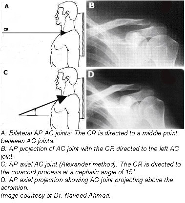
- In the Pearson method (AP projection) the CR is perpendicular to the midpoint between the AC joints for a single projection, and is directed at each respective AC joint when two separate exposures are needed for each shoulder in broad-shouldered patients.
- In the Alexander method (AP axial projection), which is superior in delineating abnormalities of AC joint, the CR is directed to the coracoid process at a cephalic angle of 15°. This angulation projects the AC joint above the acromion.
 |
Evaluation criteria for an AC joint radiograph
- Both AC joints, as well as the entire clavicles and SC joints, should be entirely included on one or two single radiographs.
- Both AC joints on the same horizontal plane; rotation should be evidenced by symmetric appearance of the SC joints on each side of the vertebral column.
- CR and center of the collimation field should be at the midpoint between the AC joints.
- Optimal density and contrast should clearly demonstrate the AC joints and soft tissue without excessive density. Bony margins and trabecular marking will appear sharp, indicating no motion.
- Right and left markers, as well as markers indicating with and without weights, should be visible without superimposing essential anatomy.
- In an AC joint radiograph taken using the Alexander method, the AC joint and clavicle should be projected above the acromion.
AuntMinnie.com contributing writer
February 18, 2003
Related Reading
Getting the most from shoulder positioning, December 24, 2002
The bends and flexures of forearm and elbow x-ray positioning, November 21, 2002
The twists and turns of hand and wrist x-ray positioning, October 15, 2002
Digit imaging requires diligent positioning, September 17, 2002
Patient positioning techniques for a lower gastrointestinal series, June 27, 2002
Copyright © 2003 AuntMinnie.com


