The latest-generation multidetector-row CT scanners are bringing stunning high-resolution images to daily clinical practice, along with exciting new diagnostic possibilities throughout the body, and particularly in the heart. Improved spatial resolution does exact a price -- in higher image noise or markedly increased radiation dose.
Still, a little creativity can yield solutions for some of the toughest challenges, according to Dr. Mathias Prokop, a professor of radiology at the University Medical Center Utrecht in the Netherlands. During a "State-of-the-Art" imaging symposium at the 2005 European Congress of Radiology (ECR) in Vienna, the noted CT expert talked about the possibilities and problems associated with the 16-, 32-, 40-, and now 64-slice machines coming into widespread use.
Scanner performance, defined as the ratio between maximum table speed and the thinnest slice that can be reconstructed, has been increasing rapidly since the 1980s. "We have seen an increase in performance by a factor of two every two years," Prokop said. By the same measure, the performance of 64-slice scanners is more than 16 times that of four-slice machines, he said.
Whether the manufacturer is GE Healthcare, Siemens Medical Solutions, Philips Medical Systems, or Toshiba Medical Systems, the hybrid-array detector configuration of the 16-slice scanners is very similarly designed -- with arrays of larger detectors on the periphery and smaller detectors in the center, Prokop said. Independent of the collimation used, all 16-slice scanners provide 16 simultaneous slices per rotation.
This is distinctly not the case with 32-, 40-, or 64-slice machines, whose detector configurations vary by manufacturer. None of these machines provides the maximum number of available detectors for the largest available collimation. For example, GE's 64-slice scanner allows for using 64 x 0.625-mm collimation, but only 32 slices at 1.25 mm. Similarly, Philips' 40-slice machine enables 40 x 0.625-mm and 32 x 1.25-mm collimation, while Toshiba provides 64 x 0.5-mm and 32 x 1-mm collimation, Prokop noted.
Meanwhile, Siemens' Sensation 64 offers a detector configuration of 32 x 0.6-mm and 20 x 1.2-mm collimation, he said. The scanner offers only 32 slices per rotation in the nonspiral or sequence mode, but Siemens calls it a 64-slice scanner because of a feature called z-flying focal spot (zFFS), which shifts the position of the focal spot relative to the detector during imaging to offer slightly different views of an object.
With zFFS technology, "during one rotation every detector sees two different focal positions, which gives two overlapping projectional datasets, and therefore, the manufacturer claims that this creates 64 slices," Prokop said. "What it definitely does do is eliminate aliasing artifacts in the z-direction" because sufficient projections are now available even at higher pitch values, he said. "The slices ... overlap by 50% in the center and still have 0.6-mm collimation. It reminds me a little bit of zero interpolation in MR, where you also create better spatial resolution by overlapping thicker sections."
The difference in clinical practice
"If you look at the advantages of 32- to 64-slice scanners over the previous generation, we can expect more reliable and more constant image quality," he said. The vast arrays of detector rows will have their biggest clinical impact in the heart, while other applications, such as whole-body and lung CT, or even combined heart/lung scans can be optimized with higher-resolution imaging, Prokop said.
 |
|||||
| Manufacturer | Collimation | Pitch | Rotation | Scan length | Scan duration |
| Chest | |||||
| Philips/Siemens | 16 x 0.75 mm | 1.5 | 0.5 sec | 30 cm | 8 sec |
| Siemens | 32 x 0.6 mm | 1.5 | 0.37 sec | 30 cm | 4 sec |
| Philips | 64 x 0.625 mm | 1.25 | 0.42 sec | 30 cm | 2.5 sec |
|
|||||
| Abdomen | |||||
| GE | 16 x 0.625 mm | 1.375 | 0.5 sec | 40 cm | 15 sec |
| Siemens | 32 x 0.6 mm | 1.5 | 0.37 sec | 40 cm | 5 sec |
| Toshiba | 64 x 0.625 mm | 1.25 | 0.4 sec | 40 cm | 4 sec |
|
|||||
| Heart | |||||
| Philips | 16 x 0.625 mm | 0.2 | 0.42 sec | 12 cm | 25 sec |
| Siemens | 32 x 0.6 mm | 0.25 | 0.33 sec | 15 cm | 10 sec |
| Toshiba | 64 x 0.5 mm | 0.2 | 0.4 sec | 15 cm | 9.5 sec |
|
|||||
| Scan duration (without overranging) for examples of typical examinations with 16- and 64-slice CT. Note that the performance of the Siemens 64-slice/32-channel scanner is in the same range as that of other 64-slice units. Data courtesy of Dr. Mathias Prokop. | |||||
Cardiac images have become faster and more stable, and cardiac gating is now available in almost any body region without having to worry too much about sacrificing either short scan duration or imaging resolution, Prokop said. More detector rows enable coverage of larger volumes when needed, and also enable the broader view of perfusion imaging. Time can easily be added as a fourth dimension when motion, in the form of cardiac motion or perfusion, is added to 3D imaging.
Another benefit is increased image quality even in challenging conditions, he said, showing a slide of a patient with vascular arrhythmia. Even though the patient's heart rate varied from 50-150 beats per minute (bpm) during the eight-second scan, the images clearly showed calcified soft plaque, and even small branches are nicely visualized.
 |
| Coronary CT in a patient with absolute arrhythmia (a) performed with 4 x 0.625-mm collimation. The heart rate varied from 40-140 bpm within the eight-second scan time. Note the soft plaques in the right coronary artery (b) and the good quality of small vessels (c). Images courtesy of Dr. Mathias Prokop. |
Using many detector rows and the thinnest collimation, radiologists can expect much higher spatial resolution in the z-direction (0.4-0.5 mm) than in the xy-plane (0.7-0.8 mm), which is quite remarkable given the fact that resolution used to be lower in z-direction than the xy-plane in earlier scanner generations, he said. This high spatial resolution can be achieved even at extremely short scan times, and will translate into sharper multiplanar reformations.
"Now the question is do we really want that (maximum speed), and the answer is no," he said, showing a whole-body image acquired in 16 seconds on a 64-detector scanner -- that had outrun the contrast bolus.
"Since we usually don't know what the patient has when we perform a peripheral CTA, that's why we do the exam. It makes sense to try to do something about the scanning speed," Prokop said. "Two solutions: use a longer delay -- wait more time before you start scanning -- or scan slower, and that's actually what we're doing. We use a lower pitch, and try to keep the whole-body scan in the range of 30-40 seconds...."
Pixel size
When the highest spatial resolution is required, pixel size will also need to be reduced, he said. Standard body imaging with a 512 x 512 matrix and a field-of-view of 350 mm will yield a pixel size of 0.7 mm, too large to take advantage of isotropic resolution of 0.4 mm or 0.5 mm. Reducing the field-of-view to 200-250 mm at a 512 x 512 matrix size, or alternatively, using a higher matrix size (768 x 768 or 1024 x 1024 on some scanners), will cut the pixel size down to the range of 0.35-0.45 mm, "the same range as spatial resolution," Prokop said.
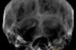
With the larger matrix size (detector width up to 4 cm), "the conebeam angle is very large, so in principle artifacts should occur, but the interpolation algorithm that is used takes care of these artifacts in most areas. But we still see some problems in the region of the posterior fossa and the skull base," he said.
Smaller pixels certainly came in handy in one proffered example: a six-second high-resolution scan of a patient with medullary thyroid cancer. The image showed multiple tiny metastases throughout the lungs, many of which were in the submillimeter range.

| High-resolution CT of the chest performed with 40 x 0.625-mm collimation within six seconds. Images were reconstructed with a 768 x 768 matrix, yielding 0.45-mm pixels that take full advantage of the increased resolution of these machines. Note the multiple small metastases in this patient with medullary thyroid cancer. Image courtesy of Dr. Mathias Prokop. |
Kernels of wisdom
Also of note is that spatial resolution in the scan plane is limited by the reconstruction kernel, which imparts a disproportionate amount of noise if resolution higher than 0.7-mm is required using a high-resolution kernel as opposed to a standard reconstruction kernel, Prokop said. Noise is not usually a problem for bone or lung imaging, but can be nettlesome for soft-tissue or cardiac imaging.
A high-resolution kernel increases the noise by 200% to 300%, "and in order to compensate for that you have to increase the effective dose by a factor of five, which is quite substantial," he said.
Thinner slices are, of course, the other major factor that increases noise and demands higher radiation doses, which reach their zenith in retrospectively gated CT angiography. At some institutions, retrospectively gated CTA has carried a dose as high as 60 mGy (CTDIvol), three to six times higher than that of nongated chest CT.
"So in-plane resolution suddenly becomes our main enemy when it comes to spatial resolution," Prokop said. "But we can trade spatial resolution for dose reduction. Through-plane resolution is sacrificed through the thick sections in body applications, and that really helps."
 |
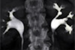
| CTA of chest, abdomen, and legs (150-cm scan length) in a patient with Leriche's syndrome examined with 16 x 0.75-mm collimation within 50 seconds. Images courtesy of Dr. Mathias Prokop. |
Dose control
"Two problems which are quite substantial and quite important are the noise increase and the trend toward dose increases in order to compensate," Prokop said. "I see these as the most important limiting factors for (MDCT) using these new scanners."
There is good news, inasmuch as dose efficiency is increasing with the number of detector rows, he said. Moving from one to four detectors required an approximate dose increase of 30% to provide the same signal to the detectors, but the transition from four to 16 detectors rose by only 10% to 15% in comparison. The increase is negligible for the transition to 32- and 64-detector machines "because we are already using the whole detector, and dose efficiency is much better," he added. A recent dosimetry study in Belgium confirmed that normalized CT dose index (CTDI) increases less and less with the use of greater numbers of detector rows, he said.
Nevertheless, reducing slice thickness for high-resolution imaging can increase the dose exponentially. "It's something that many people will do, hopefully not in clinical routine practice," he said. "But if you reduce your slice thickness (from 5 mm to 1 mm), the knockoff quanta of the CT detectors are reduced by a factor of five. The noise goes up by the square root of five, or from 100% to 224%. The only way to compensate for that is to give five times the dose, which I think in clinical practice is usually not acceptable."
In fact, he said, the maximum spatial resolution of 0.5 mm should be avoided, except perhaps in applications such as the circle of Willis area of the brain, or the region of the hand, Prokop said. High spatial resolution is also important when imaging stents, which require the thinnest collimation and reconstruction intervals, he said.
Scan thin, reconstruct thick for body imaging
For many body imaging applications, however, the solution for reducing dose is to reconstruct thick multiplanar reformatted (MPR) images from thin-section data. This technique keeps spatial resolution in the imaging plane very high, but reduces noise to a reasonable level, Prokop said.
"The question is, does it always work? And unfortunately it does not," he said. "It doesn't work in those indications where we really need isotropic resolution -- if we want to check small vessels, be able to do a centerline tracking, for example.... So (thick MPRs are) not really a solution for CTA. You probably can increase your slice thickness in the range of 1-2 mm, but not much more." This becomes a limiting factor for CTA, and even more so for coronary CTA because only part of the data is used for image reconstruction with retrospectively gated techniques, he said.
Sixteen-slice scanners are probably still sufficient for almost all body indications, while 32- and 64-row scanners offer opportunities to look at functional information, and improve visualization of the heart. But dose issues are critical and worthy of careful consideration, Prokop said.
 |
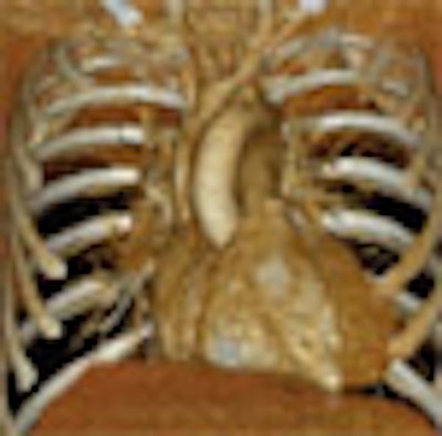
| Cardiac images reconstructed from a gated chest CT obtained with a collimation of 40 x 0.625 mm and a dose of CTDIvol = 20 mGy. Reconstructions (a) in diastole, (b) in systole. Images courtesy of Dr. Mathias Prokop. |
Perfusion imaging, for example in the brain, can now routinely cover 4 cm on some of the newer 40- to 64-slice machines as opposed to 1-2 cm in earlier scanner generations, he said. The advantage is that perfusion information from a larger brain area becomes available, which should make it possible to detect smaller infarcts or areas at risk, seen as penumbra, not only in a 1-cm slab but in larger volumes of the brain.
A four-slice scanner could already produce functional information from the heart. The new scanner generation makes it possible to combine evaluation of the lungs with evaluation of heart function without having to increase the dose substantially compared to a standard chest CT. And noise can be controlled more easily in functional imaging exams compared to standard cardiac imaging. This is also the reason why late-enhancement exams are possible with less than 1 mSv of radiation, Prokop said.
"You can take cardiac function from any chest CT because you can now easily cover the whole chest," he said. "You can do integral analysis of the aorta and the coronaries, and you can analyze cardiac function."
By Eric Barnes
AuntMinnie.com staff writer
April 8, 2005
Related Reading
Honing MRI, PET/CT protocols for larger patients, June 30, 2004
CT, radiation, and risk: two views, June 24, 2004
High pitch, thin sections can optimize MDCT protocols, August 22, 2003
Ask questions to optimize MDCT protocols, March 11, 2003
Spiral and Multislice Computed Tomography of the Body, March 10, 2003
Copyright © 2005 AuntMinnie.com