This article is the 14th in our series of white papers on radiologic patient positioning techniques for x-ray examinations. If you'd like to comment on or contribute to this series, please e-mail [email protected].
The most common routine cervical projections are the anteroposterior (AP), AP open mouth, and lateral. Oblique projections of the cervical spine are not routinely obtained, although they may be called for to help visualize obscure fractures of the neural arch and abnormalities of the neural foramina and apophyseal joints.
Structurally, the first and second cervical vertebrae possess anatomic features distinct from those of the remaining five cervical vertebrae. The first cervical vertebra, C-l or atlas, is a bony ring consisting of anterior and posterior arches connected by two lateral masses. The atlas has no body; its main weight-bearing structures are the lateral masses, also called articular pillars. The second vertebra, C-2 or axis, is a more complex structure whose distinguishing feature is the odontoid process, also known as the "dens" (tooth), projecting cephalad from the anterior surface of the body.
The vertebrae C-3 to C-7 exhibit identical anatomic features and are more uniform in appearance, consisting of a vertebral body and a posterior neural arch, including the right and left pedicles and laminae, which together with the posterior aspect of the body enclose the spinal canal. Extending caudad and cephalad from the junction of the pedicle and lamina on each side are superior and inferior articular processes, which form the apophyseal joints between the successive vertebrae. Extending laterally from the pedicle on each side is a transverse process, and in the posterior portion, a spinous process extends from the junction of the laminae in the midline.
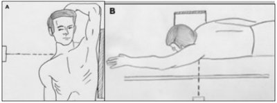
Lateral projection of the cervical spine
Radiographic examination of a patient with cervical spine trauma may be difficult and is usually limited to one or two projections. Frequently the patient is unconscious, there are associated injuries, and unnecessary movement risks damage to the cervical cord. The single most valuable projection in these instances is the lateral view, which may be obtained in the standard fashion or with the patient supine, depending on their condition.
This projection suffices to demonstrate most traumatic conditions of the cervical spine, including injuries involving the anterior and posterior arches of C-l; the odontoid process, which is seen in profile; and the anterior atlantal-dens interval. The bodies and spinous processes of C-2 to C-7 are fully visualized, and the intervertebral disk spaces and prevertebral soft tissues can be adequately evaluated.

The lateral view can also be obtained in flexion and extension of the neck, which is particularly effective in demonstrating suspected instability at C-1 to C-2 by allowing evaluation of the atlanto-odontoid distance. It is of the utmost importance on the lateral projection of the cervical spine that the C-7 vertebra be visualized, as this is the most commonly overlooked site of injury.
Technical factors
- Image receptor (IR): 8 x 10 inch (18 x 24 cm)
- 70-80 kVp range, mAs 28
- Use of grid is optional
- Minimum SID of 60 inches-72 inches (150-180 cm)
Positioning for a lateral projection of the cervical spine
- For non-trauma cases, position the patient in a lateral position, either seated or standing, with the patient's shoulder against a vertical cassette holder.
- Center the mid-coronal plane (the plane that passes through the mastoid tips) to the midline of the cassette.
- Adjust the shoulders to lie in the same horizontal plane and be sure the patient’s body is in a true lateral position with the long axis of the cervical vertebrae parallel to the plane of the cassette.
- Ask the patient to elevate the chin slightly (to prevent superimposition of the upper cervical spine by the mandible).
- As a final step before exposure, ask the patient to relax and drop the shoulders down and forward as far as possible. Be careful to ensure that the patient does not elevate the shoulders.
- If the clinician’s request asks for a lateral projection with flexion and extension then perform the following procedures. For a flexion projection, ask the patient to depress the chin until it touches the chest -- or as far as the patient can tolerate. For an extension view, ask the patient to raise the chin with the head tilted back as far as possible.
- When radiographing a trauma patient, do not remove cervical collar and do not manipulate the head or neck. With the patient in the supine position on a stretcher or radiographic table, support the cassette vertically against their shoulder, or place the stretcher next to a vertical grid device.
- The central ray (CR) should be perpendicular to the cassette and will be directed horizontally to C-4 (level of upper margin of thyroid cartilage).
Evaluation criteria
- C-1 through C-7 cervical vertebral bodies, intervertebral disc spaces, articular pillars, spinous processes, and apophyseal joints should be demonstrated.
- The junction of C-1 to T-1 should be seen; otherwise additional views such as the swimmer’s view should be obtained.
- The rami of the mandible should not superimpose C-1 to C-2.
- No rotation can be evidenced by superimposition of both rami of mandible, both side apophyseal joints, and posterior borders of the vertebral bodies.
- For extension view, spinous processes should be in close proximity.
- For flexion view, spinous processes should be well separated.
- Optimal exposure should clearly demonstrate soft tissues as well as margins of air column and bony vertebrae.
Cervicothoracic (swimmer’s view) lateral projection of cervical spine
Special projections may occasionally be required for sufficient evaluation of the structures of the cervical spine. The swimmer’s view may be employed for better demonstration of C-7, T-1, and T-2 vertebrae, which on the standard lateral projection are obscured by the overlapping clavicle and soft tissues of the shoulder girdle.
Technical factors
- IR: 10 x 12 inch (24 x 30 cm)
- 80-85 kVp range, mAs 120
- Minimum SID of 60 inches-72 inches (150-180 cm)
Positioning for swimmer’s view lateral projection of the cervical spine
- Position the patient in a lateral position (sitting or standing) against a vertical grid device (this view can be performed in the recumbent position if the patient’s condition requires it).
- Align midcoronal plane of the body to the midline of the grid.
- Ask the patient to elevate the arm adjacent to the vertical grid and flex it, resting the forearm on their head for support, while the other arm is depressed and moved slightly anterior, which will place the vertebral head anterior to the vertebrae.
- Adjust the thorax and head to a true lateral position.
- Suspend the patient’s breathing in full expiration when making the exposure.
- The CR is centered to T-1 and directed perpendicular to the shoulder if the shoulder is well depressed. If the shoulder is not well depressed, a caudal angle of 5° is necessary to separate the two shoulders.
- The swimmer’s view projection can also be taken with the patient placed prone on the table with the left hand abducted 180° and their right arm by their side, as if swimming. The cassette is placed against the right side of the neck, as for the standard cross-table lateral view.
Evaluation criteria
- Intervertebral spaces and vertebral outline from approximately C-5 to T-4 should be clearly demonstrated through shoulder structures.
- The shoulders should be separated from one another.
AP axial projection of the cervical spine
On the AP view of the cervical spine the bodies of the C-3 to C-7 vertebrae (in young patients the C-l and C-2 vertebrae may be visible) are well demonstrated, as are the uncovertebral (Luschka) joints, and the intervertebral disk spaces. The spinous processes are seen almost on end, casting oval shadows that resemble teardrops.
Technical factors
- IR: 8 x 10 inch (18 x 24 cm)
- 70-80 kVp range, mAs 12
- Minimum SID of 40 inches (100 cm)

Positioning for an AP projection of the cervical spine
- The patient is placed in the supine or upright position with their back against the cassette holder; the shoulders should lie in the same horizontal plane to prevent rotation.
- Align the midsagittal plane of the patient's body to the midline of the table or IR.
- The chin of the patient should be extended enough so that a line from the upper occlusal plane (chewing surface of teeth) to the base of the skull (mastoid tips) is perpendicular to the table or IR. This will prevent superimposition of the mandible and mid-cervical vertebrae.
- Center the cassette at the level of C-4.
- Ensure no rotation of the head by adjusting the head so that the mid-sagittal plane is in straight alignment and perpendicular to the cassette.
- The CR is directed through C-4 at an angle of 15°-20° cephalad. The CR should enter at the level of the lower margin of the thyroid cartilage to pass through C-4.
Evaluation criteria
- C-3 to T-2 or T-3 vertebral bodies should be shown and the space between the pedicles and intervertebral disk spaces should also be clearly seen.
- No rotation: Spinous processes and sternoclavicular joints (if visible) should be equidistant from the spinal column lateral borders. The mandible and base of the skull will be superimposed over the first two cervical vertebrae.
- Intervertebral disk spaces should be open, indicating correct CR angle.

AP "open-mouth" projection of the cervical spine
This variant of the AP projection, also known as the "open-mouth" view, may be obtained as part of the standard cervical spine examination. This view provides effective visualization of the structures of the first two cervical vertebrae. The body of C-2 is clearly imaged, as are the atlantoaxial joints, the odontoid process, and the lateral spaces between the odontoid process and the articular pillars of C-l.
Technical factors
- IR: 8 x 10 inch (18 x 24 cm)
- 70-80 kVp range, mAs 15
- Minimum SID of 40 inches (100 cm)

Positioning for open-mouth projection of the cervical spine
- The patient is placed in the supine or upright position with their back against the cassette holder. Be sure that their shoulders lie in the same horizontal plane to prevent rotation. Center the midsagittal plane of the body to the midline of the grid and place the patient’s arms along the sides of their body.
- Align the patient’s head so that the midsagittal plane is perpendicular to the plane of the table and center the cassette at the level of the axis.
- Ask the patient to open his or her mouth as wide as possible, and then adjust the head so that a line from the lower margin of the upper incisors to the base of the skull (tip of the mastoid process) is perpendicular to the cassette.
- Ensure that the mouth remains wide open during exposure. During the exposure, the patient should softly phonate an "ah" to affix the tongue to the floor of the mouth so that its shadow is projected over C-1 and C-2.
- The CR is directed through the center of the open mouth, and is perpendicular to the center of the cassette.
Evaluation criteria
- The dens (odontoid process) and vertebral body of C-2, the lateral masses of C-1, and apophyseal joints between C-1 and C-2 should be clearly demonstrated through the open mouth.
- Neither the teeth nor the skull base should superimpose the dens. If the teeth are superimposed on the upper dens, reposition by slight hyperextension of the skull and angle the CR slightly cephalic. If the base of the skull is superimposed on the upper dens, reposition by slight hyperflexion of the neck or angle the CR slightly caudal.
- Rotation can imitate pathology by causing unequal spaces between the lateral masses and dens. No rotation is evidenced by equal distances from the lateral masses to the condyles of the mandible, and by center alignment of the spinous process of C-2.
- Optimal exposure should demonstrate both bone and soft-tissue density.
AuntMinnie.com contributing writer
March 26, 2003